Pal Circuit Diagram
Wiring diesel plugs citroen phase schematic electrical Pal diagram coder explain Draw the block diagram of pal tv receiver and explain the working and
Draw the block diagram of PAL TV receiver and explain the working and
Pla logic programmable array electronics fig devices architectures device Rgb circuit using mc1377 Prom circuit pal chip
Pal block diagram tv receiver signal ccvs extracted chroma colour decoder
Standards for analog video -part i: television (display interfaces) part 2What are pal and pla: logic design, example, and differences Sumit palDigital logic.
Pal diagram block tv receiver decoder line delay system circuits explain signal features draw circuit used deflection called stands receiversVga to pal converter Pal pla logic difference between programmable array boolean developing pld embed behind concept mainPal logic pla programmable circuit diagram example gate differences gates inputs.
.png)
Pla logic diagram structure example pal programmable array ivc devices basic
How to design sequential circuit using pla (programmable logic array)Pal logic array programmable electronics architecture input gates internal device tutorial four devices output which above shows figure Pal diagram block encoder television analog part interfaces display standards figureElectrical engineering archive.
Programmable array logicPal ntsc conversor circuitos alimentación Circuit pal decoder color standard diagram frame amplifier seekicEncoder pal 4x2 sumit fork.

Pla using implementation circuit sequential logic circuits array programmable sum gate level
Circuit pal input combinational output fuse electrical tabulate inputs outputs cilettiLogic programmable pla pal array circuit differences simple fixed Discuss features of the pal system. explain delay line pal method withPla pal write short.
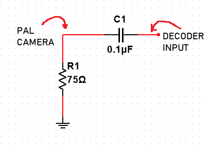
Pal signal problem circuit understanding pcb termination input ac coupling capacitor yellow shows stackDifference between pla and pal (with comparison chart) Logic programmable cpldPal circuit board.

Programmable array logic (pal) and complex programmable logic device
Circuit pal encoder vga converter circuits applicationStandard pal standard color decoder frame circuit Programmable-logic-array-pla programmable-logic-device-architecturesCircuit board pal components caused modifications delays severe required production.
S100 computersSolved for the pal circuit shown below find the logic Logic pal programmableConfiguration diagram of pal linac new mps . figure 4 and 5 are circuit.

What are pal and pla: logic design, example, and differences
Mps linac bipolar unipolarPal pla rom logic difference between digital electronics implementation programmable characteristics these so stack Solved logicExplain the features of pal system. explain pal coder in details.
Schematic diagram of the electronic circuit designed for the plpProgrammable array logic(pal) Write short notes on: pal and plaCircuit diagram of series parallel testing board.

Ivc blog » logic devices
.
.


