Phasor Diagram Lrc Circuit At Resonance
Diagram represents phasor solved circuit below capacitor resistor rlc unknown using transcribed problem text been show has determine inductor given Phasor diagram for lrc circuit Phasor rlc represented chegg
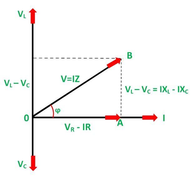
Phasor Diagram of Series RLC Circuit The
Phasor diagram circuit lrc Diagram phasor circuit rlc series chapter globalspec Solved problem 2 the diagram below represents the phasor
41 rlc circuit phasor diagram
Phasor rlcPhasor diagram of parallel rlc circuit 41 rlc circuit phasor diagramPhasor circuit rlc parallel diagram.
Lr circuit, with phasor diagramRlc phasor Solved the diagram below represents the phasor diagram forPhasor diagram at r, l and c in ac -circuit.

Diagram phasor circuit rlc series phase figure chapter globalspec
Phasor circuit diagram lr ac teaching eng ed41 rlc circuit phasor diagram Phasor which resonance represents driven circuit diagrams shown below lrc series transcribed text showSeries resonance in a series rlc resonant circuit.
Rlc phasor electrical4u circuito diagramsSolved: which one of the phasor diagrams shown below best Phasor diagram rlc circuit combined passive networksPassive networks.

Phasor rlc circuits impedance voltages computations
Circuit phasor diagram rlc series inductor capacitor resistorSolved: the phasor diagram for an rlc circuit is shown in Phasor diagram rlc series wolfram demonstrations circuitsSeries rlc circuit analysis-phasor diagram.
Phasor diagram for series rlc circuitsDiagram phasor problem solved represents voltage transcribed text been show has phase power Circuit rlc phasor diagram shown if resistance figurePhasor diagram of series rlc circuit the.

41 rlc circuit phasor diagram
Rlc resonant resonancePhasor rl inductor explaination difference begingroup Rlc series circuit.
.


