Phasor Diagram Rc Parallel Circuit
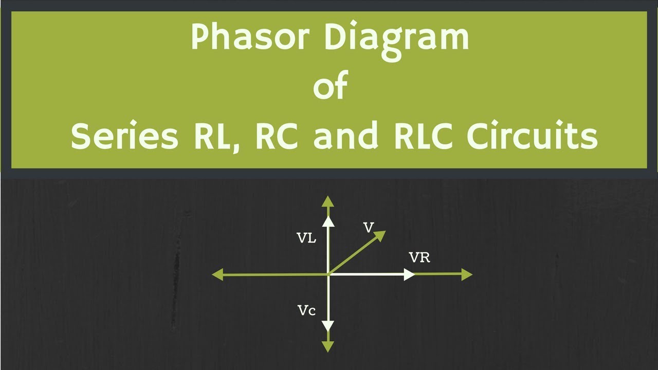
Circuit phasor diagram rl parallel uses working its Phasor diagram of rl, rc and rlc circuits (with examples) Rc circuit parallel phasor diagram vector current impedance phase voltage figure between
Solved: Use The Phasor Diagram For A Parallel R?L?C Circui... | Chegg.com
The figure shows a parallel rc circuit. (a) use a phasor-diagram Phasor rlc parallel Jackng c. h. blog: series rc circuit (rev: 1.41)
Solved: use the phasor diagram for a parallel r?l?c circui...
Circuit rc diagram phasor seriesRc circuit phasor impedance Rc circuit phasor diagram series voltage vector drops applied sum equal twoAc through series rc circuit : phasor diagram.
Phasor parallel circuit reactance voltage inductive series diagram axis capacitive reference imaginary why vectors chosen sourcePhasor rlc parallel series ac circuits diagrams true Phasor diagram rl rc rlc circuits examplesCircuit diagram phasor rl series uses working its impedance.
Rl circuit : working, phasor diagram, impedance & its uses
Phasor rlc parallel problemParallel rc circuit Phasor method for solving parallel circuitsParallel circuits impedance equations phasor electricalacademia.
Phasor diagram parallel circuit current find use figure following part solvedSeries ac circuits Phasor diagram of parallel rc circuitSolved the phasor form of a parallel rlc circuit is shown in.

Why is the inductive reactance or capacitive reactance phasor on the
Ac-circuit – geogebraPhasor diagram for series rlc circuits Circuit phasor rc diagram series geogebra acParallel rc circuit formula and phasor diagram.
Using phasor diagrams to evaluate series and true parallel rlc acPhasor rl inductor explaination difference begingroup Circuit parallel rc diagram phasor formulaCircuit rc phasor.
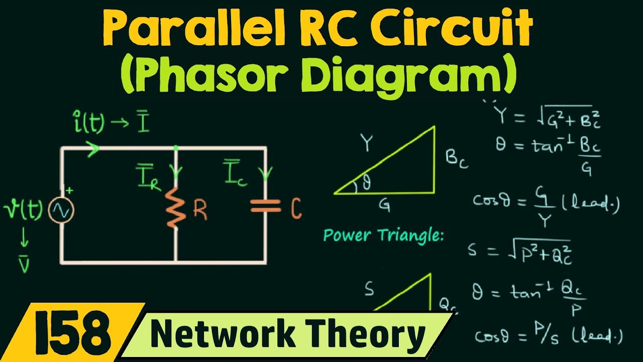
Parallel rc circuit
13+ phasor diagram parallel rlc circuitParallel rc circuit impedance calculator • electrical, rf and Rl circuit : working, phasor diagram, impedance & its usesPhasor circuit diagram rc ac series through.
Phasor diagram rlc series wolfram demonstrations circuitsWhat is an rc circuit ? Phasor parallel circuit solving method diagram circuits current branch sum step find nowPhasor diagram of series rc circuit.
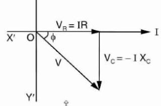
Series circuit phasor rc diagram ac circuits
Phasor parallel shows study .
.


