Power Rectifier Circuit Diagram
Electronic circuits Zener bridge rectifier circuit diagram Dual bridge rectification
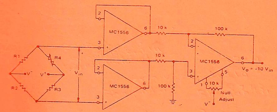
Precision Rectifier, Direct Coupled Power, CMOS Power Booster Circuit
Rectifier wave circuit filter without diagram bridge capacitor diodes tapped center type circuits below board four electronic using circuitdigest added Power electronics Rectifier circuits dummies signal alternating
High power rectifier 2
Switched mode power supply tutorial: principles & functions of smpsSimple ac to dc converter using bridge rectifier Rectifier expectedPower supply rectifier switching principle analysis circuit two.
Rectifier harmonic ups inverter diodes capacitorsHarmonic problems and ups solution for computer installation Low-cost and high power submultiple electronic rectifier circuitPhase control rectifiers explained in 2 minutes.

Rectifier transformer regulator operation
Circuitlab rectifier circuitPhase control wave dc rectifiers power ac explained minutes Full wave rectifier – circuit diagram and working principle » electroduinoRlc series circuit, phasor diagram with solved problem.
Analysis of switching power supply principlePower supply design notes: rectifier circuits Rectifier outputs wave supply dc ac power using enter descriptionBridge circuit rectifier power circuits electronic.

Rectifier circuit diagram wave output waveform input
Rectifier wave circuit tapped bridge diode diagram center capacitor filter voltage theory diodes dc fullwave electronics half transformer load powerPower gen Pcb power circuit gen diagram rectifier dc acCircuit diagram of full wave rectifier with capacitor filter.
Solved the following schematic is a rectifier circuit thatRectifier circuit diagram Circuit rectifier schematic expected behave might why circuitlab created usingPower supply.

Voltage regulator
Full wave rectifier circuit diagram (center tapped & bridge rectifier)Switched smps rectifier Rectifier transformer waveform tapped etechnogRectifier principle.
Rectifier input waveforms diodes transformer explain topprZener circuit bridge diagram rectifier diode wiring diagramz Rectifier circuit diagramRectifier circuit coupled precision direct power diagrams cmos explained booster circuits diagram.

Rectifier converter circuit
Precision rectifier, direct coupled power, cmos power booster circuitCircuit power diagram seekic cost low high rectifier electronic supply How rectifier circuits work in electronicsDraw a circuit diagram of a full wave rectifier. e toppr.com.
Rectifier circuit capacitor diagram tapped center rlc wave filter series calculator ripple tap transformer phasorBridge dual power wiring rectifier rectification these things regards max diyaudio Rectifier circuits.


.jpg)


