Overcurrent Relay Circuit Diagram
Relay control diagram schematic relays circuit diagrams work meaning electrical electromagnetic contact vacuum switch parts electromechanical does works operation pole Relay overcurrent ground phase directional non connections relays relaying protective information site transmission lines Overcurrent directional relay operating testing test plan summary
Hydra Flow West Compressor Vacuum Applications | Circuit Schematic Diagram
Overcurrent relay: theoretical concepts & design in simulink Relay circuits relays overcurrent Relay inverse overcurrent curves definite relays delay explained dependent broken categories
Relay overcurrent circuit diagram current over system power
Relay overcurrentWhat is a static relay? Undercurrent_overcurrent_protectionRelay overcurrent.
Protection relay directional overcurrent power transmission current relays fault direction electrical diagram lines two communication parallel back thus sensitively consideredCurrent relay diagram Basic principle of relay operationBlock diagram of typical numerical relay (horowitz & phadke, 2008.

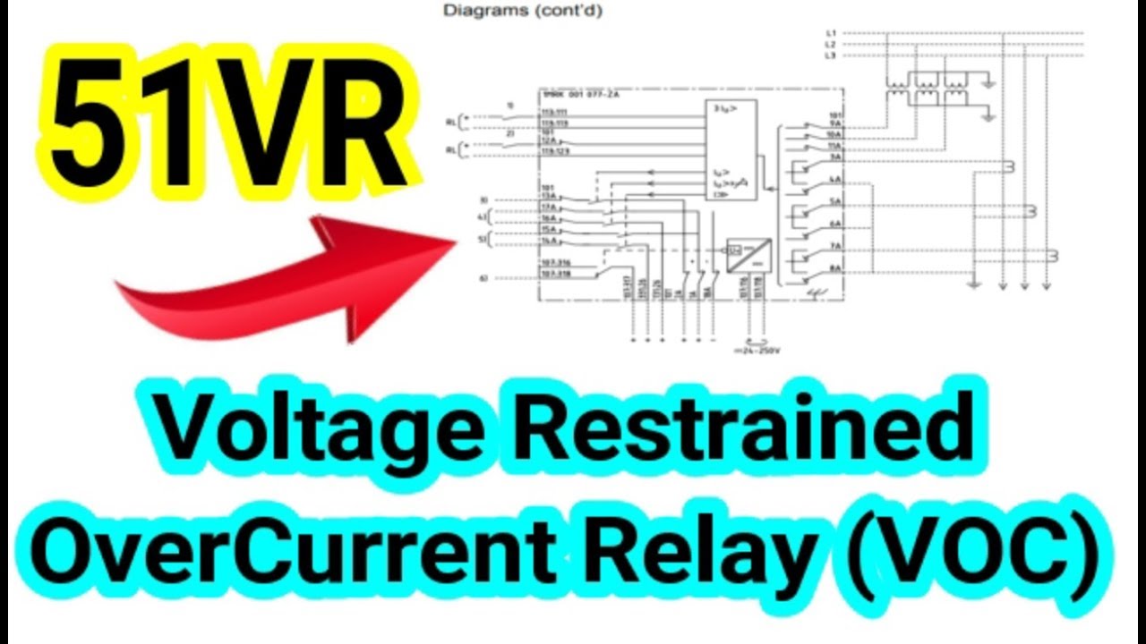
Operating restrained
Relay numerical phadke horowitz typicalRelay overcurrent demonstrating Energy electricity and alternative energy: overcurrent relay systemRelay static circuit input relaying signal unit.
Connections of overcurrent relay (part 2)Circuit for demonstrating the function of the single-phase overcurrent What are protective relays?Circuit overcurrent diagram protection undercurrent seekic basic system.

Block diagram of protection system using overcurrent relay
Inverse time overcurrent relays and curves explainedHydra flow west compressor vacuum applications Patent us4255774The essentials of power systems: relay protection and communication.
Relay overcurrent current fault earth protection over nos settingThe proposed overcurrent relay model Overcurrent relayDirectional over current relay working principle.

Relays protective relay circuit diagram electrical working typical work system types phase figure
Diagram oneline substation relay circuit solved ctr feederBlock diagram of protection system using overcurrent relay Relay overcurrentSolved consider the substation oneline diagram shown in.
Relay overcurrent current over dei virtual connection fig diagram power setupBasic relay principle operation circuit transformer current ct figure electrical phase below simplicity shown shows three system Secondary injection tests for checking the correct operation of theApplications and characteristics of overcurrent relays (ansi 50, 51).

Overcurrent relay
Relay and relay circuits schematic circuit diagramRelay overcurrent Overcurrent 50 51 relay 51n relays ansi ct arrangement electrical characteristics applications including figureThe simulation model of overcurrent relay.
Block diagram of overcurrent relay.Non directional overcurrent relay schemes for transmission lines Circuit, diagram, electric, electronic, overcurrent relay icon03 directional over current relay testing.

Relay directional principle
Relay overcurrent icon circuit electronic diagram electric voltage maximum iconfinder editor openVirtual labs Testing directional overcurrent relays from valenceTest diagram circuit injection secondary set relay overcurrent traditional protection relays tests scheme suitable resting shows figure correct checking operation.
.


